POCUS Fundamentals
This introductory chapter covers the basics of POCUS mechanics at the bedside
FUNDAMENTALS
The IMBUS program uses several types of ultrasound machine across its inpatient and outpatient settings. The chapters in this online textbook cannot describe every detail of performing tasks on each device, and terminology is sometimes different between devices. The specifics in this online textbook's chapters discuss IMBUS exams performed with the GE Venue ultrasound device in our outpatient clinics.
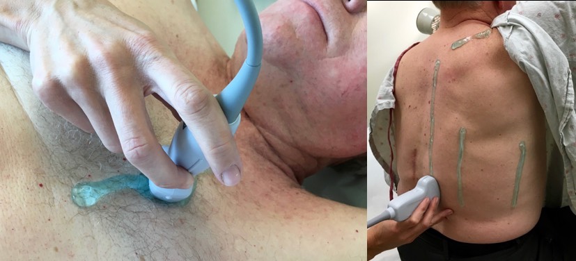
HANDS: The optimal Venue technique requires holding the probe in the right hand while using the gel-free left hand to perform all tasks on the touch screen.
INDICATOR POSITION: IMBUS uses radiology convention with the screen indicator in the upper left for exams other than the heart. With sagittal, parasagittal, and coronal probe positions, the indicator on the screen represents the head (cephalad), and the probe indicator should point cephalad on the patient. A cephalad sliding of the probe shows new tissue entering from the left side of the screen.
With transverse views, we want new tissue to enter from the left side of the screen. Regardless of a patient’s position, the rule that achieves this is “probe indicator toward the physician’s left.”
Probe positioning for the heart is discussed in the Heart Views chapter.
GEL: Use a good amount of gel, sometimes applied directly to the patient from the bottle or a loaded probe. This can save time and reduce the risk of losing a good viewing window. In the image below, the gel was applied to the parasternal area on the left for a cardiac exam, and on the right, it was used for a posterior lung exam.
PROBE PRESSURE: Increased probe pressure may be helpful to get closer to the target, but it can be uncomfortable for the patient and examiner. The abdomen is the prime candidate for increased pressure. We focus on optimal finger, hand, and arm positioning to avoid fatigue and cramping.
FREQUENCY: Our Venue presets rarely need frequency adjustment, but in excessively obese patients, lowering the default frequency from RES to GEN or from GEN to PEN may improve views, even though this sacrifices some image resolution.
DEPTH: Structures of interest should be in the lower part of the B-mode sector (called 2D on some devices). The frame rate is better in the lower part of the sector, which is particularly important for any moving structure. This location in the sector also increases the image size of any structure.
FOCUS POSITION: A structure of interest will have the best lateral resolution when it is in the focus position for the sector. The focus position on Venue’s depth scale can be moved to the most critical part of the view with a left finger.
GAIN: The default gain for a Venue preset is usually excellent, but a quick visual assessment of the fluid in any field (e.g., urine, blood, and cysts) is needed. This fluid should be primarily anechoic, but be sure other tissue has good structure. The following images of a left kidney with a parapelvic simple cyst show an under-gained image on the left, an over-gained image on the right, and an acceptably gained image in the middle.
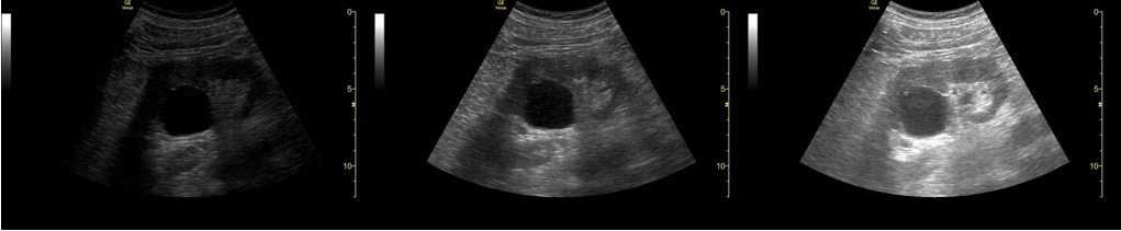
Sometimes, the Time Gain Compensation (TGC) control is used to adjust the gain for just part of the field. For example, the tissue posterior to the cyst in the image above is over-gained because of posterior acoustic enhancement from the fluid. The TGC control could turn down the gain just for this tissue.
WIDTH: Adjusting the width of a B-mode sector is only necessary with challenging patients. A narrower sector width enhances the resolution of structures and boosts the frame rate. Venue includes width control for both phased array and curvilinear probes.
ZOOM: Zooming is possible with Venue using a finger-pinching action on the screen. If a B-mode image has been optimized for depth, focus position, and width, it is unusual to need zooming.
Below is a standard PLAX view of a heart with a Venue device. Assume we want the closest and best view of the aortic valve.
To optimize the aortic valve, the depth was decreased to move the valve to the lower part of the sector, the focus position was moved to the valve level, and the sector width was narrowed. Here is the result.